Introduction
As a part of the preservation policy at the National Museum of Denmark, the laboratory at the Department of Conservation wishes to develop a protocol for the approval of all construction materials before use in storage or exhibition areas. A part of this plan involves the construction of an emission test unit for specific determination of emission products from such materials. The author is responsible for the engineering of the unit, this is done as part of the author's M.Sc thesis work at the Danish School of Conservation.
The principle of emission test units
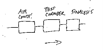
When testing construction materials for emission, the actual design of the chamber test unit is of great importance in order to be able to get useable results. But very often when checking the standards and literature on emission chambers, the description of the actual laboratory set-up is very limited, like shown at figure 1. In principle, the three main elements of an emission chamber setup are a source of air, a chamber, and a sampling system. At the National Museum of Denmark a test chamber has been constructed just recently, and that design is shown in detail in figure 2.
Figure 1. Typical diagram of chamber set-up
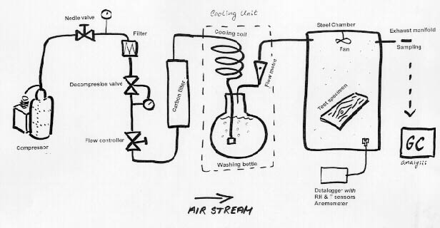
Figure 2. Emission test unit at the National Museum of Denmark
The air supply
The air source must supply the chamber with very clean air, conditioned to a well-defined temperature and relative humidity. Furthermore, it must deliver this air in a very uniform flow. Standards often advise a flow-rate which gives approximately 1 h-1 air exchange of the chamber, therefore, the flow-rate actually depends on the chamber volume. The easy part is to make a uniform flow of air. The painful part is to condition this air to a uniform temperature and RH.
Flow
At the National Museum's set-up the air stream is powered by a compressor, which delivers the air at about eight bar. The air is filtered for dust, water and oil droplets, and decompressed to ambient pressure. Flow is controlled by a Moore 64BU Flow Controller fitted with a needle valve. In this particularly set-up the chamber has a volume of 227 L (description of chamber below), thus, the flow rate required for an air exchange of 1 h-1 is 3.75 L/min. It is desirable also to include at least one flow meter somewhere in the air stream to monitor the flow rate.
Air Condition
The main purpose of the conditioning unit is to regulate the water content of the air. The system relies on the principle of saturating cold air to 100%RH, and thereafter raising the temperature until the desired (lower) relative humidity is reached.
The optimal (cool) temperature for saturation was found by consulting a psychometric chart. As almost all standards suggest test conditions of 23°C and 45 or 50%RH, the parameters 23°C +/- 1°C and 45%RH +/- 5%RH were chosen. Air with these properties has a dew-point of 11°C, so this will be the temperature needed for the saturation. Saturation is achieved by bubbling air through water, and the cooling effect is simply achieved in the same action, as the energy used to dissolve air in water is enough to cause the desired decrease in temperature. Regulation of the temperature level at the cooling unit is simply a matter of controlling the degree of insulation around the washing bottle (figure 3).
Figure 3. Cooling unit
Reheating is achieved by keeping the overall room-temperature at 23°C, the mass of the steel chamber ensures a fast and steady temperature correction. This can be problematic in the middle of summer, when room temperatures might exceed 23°C; in winter, when the room temperature might be lower, the air stream must be heated. This can be done by adding an electric heating coil to the air inlet-manifold of the chamber. The compressor is supplying all power needed to force air through the system, and to generate the cooling effect of the air conditioning.
Purification
Purification is done by blowing the air stream through a cartridge filled with activated charcoal pellets. Here, the difficult task is to keep the air clean until it is delivered into the chamber. A very high standard of cleaning must be performed on all fittings, tubes, etc. between the filter and the chamber. Prior to a test run all surfaces are washed with an alkaline detergent (Merck Extran) followed by rinsing with distilled water. Small parts are cleaned in an ultrasonic bath or by baking.
The Chamber
The chamber must be made of a chemically inert and non-emissive material, with no sink-effects. It is an advantage if the inner surfaces are smooth and easy to clean. Often glass or stainless steel is proposed in standards. Steel is probably the best choice as glass might act as a sink despite of what the standards recommend. The chamber used in the setup at the National Museum is a stainless steel chamber.
This was another painful dilemma, as glass first seemed the perfect solution. It seemed practical to be able to look into the chamber and see the test specimen, or check for instance if the fan is working. Also, it would be easier to construct a chamber in glass, and the cost was lower than a steel construction. But in order to make a glass construction also other materials must be used, silicone etc., which might be a pollution source and might be difficult to clean throughout. A steel chamber can be made of steel only. In the end stainless steel was chosen.
In the chamber two factors are especially important to control: that the air is mixed thoroughly at all times, and that the air velocity over the surface of the test specimen is controlled. The latter is important because the emission rate depends on the air velocity, especially when emission is controlled by evaporation. A small fan can be applied in the chamber for this purpose, such as the type used for cooling computer-processors.
For emission test chambers there is no preferred size or shape in the standard descriptions, since it is the loading of the total surface of the material to the chamber volume that determines the equilibrium concentration. However, it must be remembered that larger chambers therefore require larger test specimens. The term "small-scale" chambers covers anything less than ca. 5 m3.
Sampling
Sampling is performed at the exhaust manifold. At the National Museum headspace analysis using Solid Phase Micro Extraction (SPME) is carried out. The SPME-technique depends of sampling the target compound(s) on an absorbing polymeric phase, coated onto a silica fibre, which, after exposure, is directly transferred to a GC injector for desorbtion and analysis. In theory any application is possible at the exhaust, for instance sampling on an adsorbent such as charcoal or Tenax followed by chromatographic analysis. If a pump is used to collect air for sampling from the exhaust manifold, it is advisable to collect only less than 50% of the total exhaust flow, to avoid drawing "false air" into the system or otherwise disturb the system too much (figure 4).
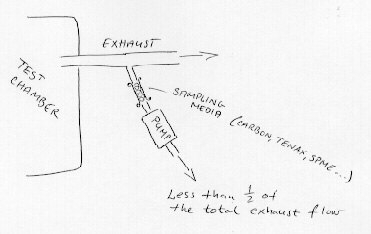
Figure 4. Sampling at exhaust manifold
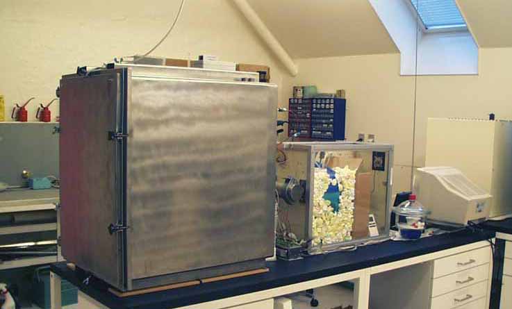
Figure 5. Chamber and air supply
Calibration
It is important to be able to monitor the various parameters of the set-up, in order to be able to control the sampling conditions. The air flow is monitored by several ball flow-meters in the air stream. They are themselves calibrated at regular intervals with a soap bubble flow-meter, which is also used to measure the exhaust flow. The temperature is measured at the cooling unit and in the chamber, using dataloggers with thermocouple sensors. The dataloggers also collect RH readings from the chamber. Air velocity in the chamber (at the surface of the test specimen) is measured with a hot-wire anemometer (SWEMA Air 30).
APPENDIX:
Some technical notes for the calculation of a material's emission rate
When equilibrium between the emission rate from the test specimen and the emission flow out of the chamber is reached, a simple mass balance is reached within the system where:
(1) Mass of emission products from material = Mass of emission products in exhaust air
Assuming that the emission rate is constant, and ignoring sinks and leaks. Furthermore, assuming that the physical conditions such as the air exchange rate in chamber, air velocity over test specimens' surface, temperature, and RH are kept at a constant level.
The time needed to reach this steady state can be checked by sampling pollutants repeatedly until the sampling results are uniform. The time needed can also be calculated. Following the above assumptions, the pollution concentration build-up in the chamber at any time, Ct, can be described as:
(2) Ct = Cst (1 - e-Nt)
where:
Ct = concentration at the time t
Cst = steady state concentration with constant air flow through chamber [µg/m3]
N = air exchange rate [h-1]
t = time [h]
In theory, it will take infinity time to reach the equilibrium concentration state. But, if for practical reasons, it is decided that a concentration of 99.9% of the equilibrium concentration is "close enough", the time t needed to reach this equilibrium concentration is found from equation 2 as:
(3) 0.999 = 1 (1 - e-Nt) => t = 6.9 / N
Following this, it is normally assumed when performing climate chamber emission tests, that the equilibrium concentration is reached after approximately seven air exchanges - if the emission rate from the material is constant. Most often it is not, but it may be assumed constant during the relatively short time intervals needed for sampling. Please note that for materials which rapidly decreases in emission rate, eg. primary emissions from a drying paint film, equation 2 is not valid.
The mass balance described in equation 1 is useful when the emission rate of pollutants from a material are to be determined. When sampling, often just a fraction of the exhaust air is collected, therefore, the mass balance is:
(4) Mass of pollutants emitted / t = ms (F / Vs)
in which:
ms = mass of sampled pollutants [µg]
F = flow rate of exhaust air [m3/h]
Vs = volume of air sample [m3]
Taking the area of the test specimen in account, the emission rate, ER [µg/m2 h], can be calculated as:
(5) ER = ms (F / Vs) / A
with:
A = total surface of test material [m2]
Assuming the system is without leaks, the flow rate in a chamber with volume V [m3] is given by F = V x N. Furthermore, the loading, L [m2 /m3], is the ratio of total surface of test material, A, over chamber volume, V. Thus the above equation can be rewritten into:
(6) ER = N (ms / Vs) / L
(in which ms / Vs = Cst)
LITERATURE
STANDARD SPECIFICATIONS FOR EMISSION TESTS
ASTM (1997) D 5116-97: Standard Guide for Small-Scale Environmental Chamber Determinations of Organic Emissions From Indoor Materials/Products. American Society for Testing and Materials, West Conshohocken PA, 14 pp.
CEN env 13419-1: Building products - Determination of the emission of volatile organic compounds: Emission test chamber method. 1999
Dansk Standard (1994) DF/INF 90: Direction for the determination and evaluation of the emissions from building products. Dansk Standard, Copenhagen. (Mainly in Danish).
Gunnarsen, Lars, Nielsen, Peter A., and Wolkoff, Peder (1994) 'Design and Characterisation of the CLIMPAQ, Chamber for Laboratory Investigations of Materials, Pollution and Air Quality'; Indoor Air, 4, Munksgaard, pp. 56-62.
NORDTEST (1990) Building Materials: Emission of Volatile Organic Compounds, Chamber Method. NT Methods BUILD 358, NORDTEST, Finland, ISSN 0283-7153, 5 pp.
Tichenor, Bruce A. (1989) Indoor Air Sources: Using Small Environmental Test Chambers to Characterise Organic Emissions from Indoor Materials and Products (Project Summary: EPA/600/S8-89/074). United States Environmental Protection Agency, Air and Energy Engineering Research Laboratory, 4pp.
Wolkoff, P., Clausen, P.A., Nielsen, P.A., Gustafsson, H., Jonsson, B., and Rasmussen, E. (1991) 'Field and Laboratory Emission Cell: FLEC'; Healthy Buildings, IAQ '91, Washington DC, American Society of Heating, Refrigerating and Air-Conditioning Engineers Inc (ASHRAE), pp. 160-165.
Wolkoff, P., Clausen, P.A., Nielsen, P.A., Gunnarsen, L. (1993) 'Documentation of Field and Emission Cell "FLEC": Identifiaction and Emission Processes from Carpet, Linoleum, Paint, and Sealant by Modelling'; Indoor Air, 3, Munksgaard, pp. 291-297.
Wolkoff, Peder, and Nielsen, Peter A. (1993) Indoor Climate Labelling of Building Materials; National Institute of Occupational Health, Copenhagen, ISBN 87-7534-443-2; 81 pp.

[ Page up ] [ IAP Group homepage ] [ Main IAQ in Museums homepage ] [ Search site ]
Indoor Air Quality in Museums and Archives
© May 11th, 2000